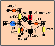
The schematics:
The list of components: registers, capacitors, transistor and etc.
- the basic unit:(pdf) (jpg)
Given the most simplest model, it is a bit inconvenient to change the transmitting frequency: change the gap of the coil (closer gap -->lower frequency; looser-->higher).- the standard model:(pdf) (jpg)
In this version, you can change the frequency by the trimercap (variable capacitor). If you can have a variable capacitor, I recommend you to choice this version.
- the standard model with a microphone: (pdf) (jpg)
This has a condenser microphone unit in it. Every version could use the same circuit. Usual microphone has not enough output to this unit, but condenser microphone unit can drive this system. See how simply it is installed--->picture
The basic tools: soldier (less than 30 watts), wire-cutter, tweezers, and etc.
How to build and solder? A visual manual.
Pictures of the finished model: Standard model
Q: Can I change the frequency of the "basic" version? How?
A: In order to change the transmitting frequency without the trimcap, you a bit spread or compress the gap of the coil. When you do this operation, you have to have some distance (at least 3 meter) between the transmitter and the receiver (FM radio): otherwise you may be disturbed by many "spurious" (harmonic signals) and may not find the main one you want. That's why the best thing is to use a frequency counter.
Q: What is "trimmercap" in "the changable-frequency version"?
A: Don't mix it with "variable capacitance diode (varicap)" for the 1-3 W transmitter. What we need here is only for manually varying the capacitance from (theoretically) 0 to 20 PF max. There are the various types and appearances. The classical one consists of tiny brass plates and ceramics. Some of the pictures are here.
Q: How to make a coil by myself?
A: Prepare a 5mm diameter cylindrical material and enameled wire of 0.8 mm diameter. The movie shows how to do.
Q: I prefer to use a tunable mold coil. What kind of coil can I use?
A: I stopped showing the schematic with it because the tunable mold coil (3-4 turns) has become less obtainable now. If you can get it, just install it instead of a hand-made coil WITHOUT the trimmer capacitor.
Q: Can I build transmitter that a microphone is attached to in it?
A: You can get a "condenser microphone unit" in low price. Using this, you can build it very easily. Check the partial diagram (pdf) and
the complete diagram(pdf) of the simplest transmitter with a microphone in it. When this is acrobatically soldered, here(jpg) is the example.
Q: When I connect my iPod to the audio input of this transmitter, it suddenly stops to work. What's happening?
A: The earlier model of iPod has an automatic shut-down system in it. When you pull out the plug of your headphone, it automatically stops working. When the left and right channels are short-circuited, the same thing happens. Presumably, you use a stereo cable and soldered the left (white) and right (red) lead together. Please use the left channel lead (white) only. Usually the left output is compatible with mono audio. If you, however, insist to mix the left and right output of your audio source into the transmitter, make a simple "interface" like this by two sets of 1 kiro ohm registers.